 Diagram
Exploded view drawing: what it is, examples, and how to make one
An exploded view drawing shows an object with its parts pulled apart along the direction they go together, so you can see every part, what sits inside what, and the order of assembly. Each part is numbered or labelled, and a parts list says what each number is. This guide walks through the parts of an exploded view, four worked examples (an engine, a flat-pack bookshelf, a house and a small computer), and how to draw one by hand or have an AI tool draw it for you.
Make your own in two minutes
- Add Diagram to Claude or ChatGPT. Free, about a minute, nothing to install: get started.
- Paste this, with your object and its parts filled in:
“Draw an exploded view drawing of my ___ . The parts, in the order they go together: ___ . Pull them apart along one axis, number each part with a balloon and a leader line, add dashed explode lines and a parts list, and give me a link.”
You get a link to the drawing that you can open, print or share. Ask for changes in plain words (“make the piston the highlighted part”) and the same link updates. The drawings below were made a slightly different way, with a coding tool and a free skill, described further down.
Make one like this
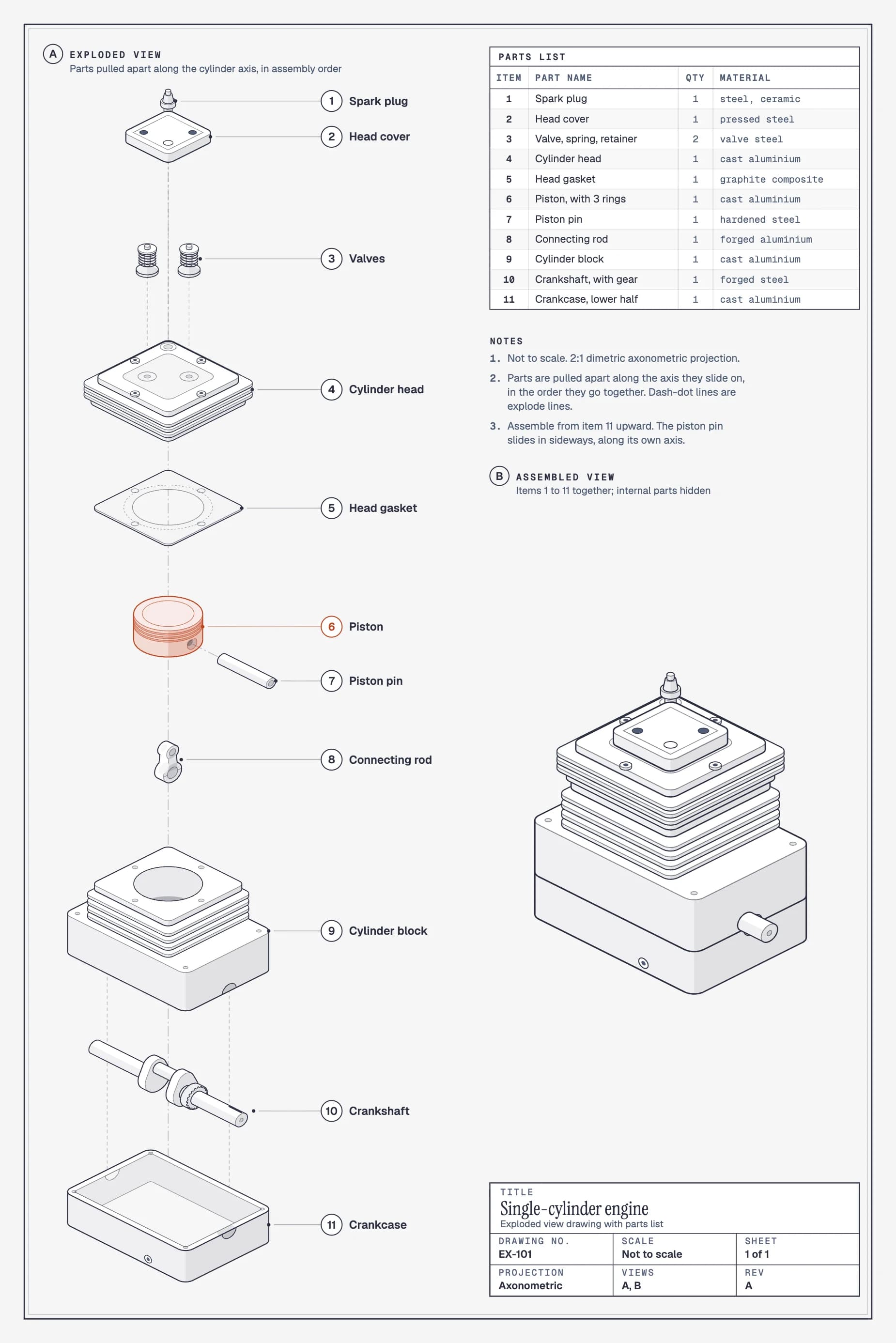
“Draw an exploded view drawing of a small single-cylinder engine on a drawing sheet. Pull the parts apart along the cylinder axis, from the crankcase up to the spark plug. Number every part with a balloon, add dashed explode lines, a parts list with quantity and material, a small assembled view and a title block.”
What is an exploded view drawing?
Picture an object taken apart and every part floated a little way out from where it sits, all along the same line. That is an exploded view. Nothing is rotated or rearranged: each part keeps its orientation and simply moves out along the axis it would slide in on, so the drawing reads as the assembly order. Read the engine above from the bottom up and you have the order a mechanic would build it in.
Exploded views are everywhere once you look: furniture instructions, repair manuals, the parts diagrams in a service catalog, patent drawings, product launch pages, and the layered building drawings on architecture boards. They go by several names: exploded diagram, explosion drawing, exploded assembly drawing, or exploded axonometric when the drawing uses an axonometric projection.
The parts of an exploded view drawing
A good exploded view is more than parts floating in space. Look back at the engine and you will find the same five things that make every exploded view in a manual readable.
The explode axis and trace lines
Every part moves along one axis, usually the direction it is assembled from. Thin dashed lines, called trace lines or explode lines, run along that axis through the parts, so the eye can follow where each one goes back in. In the engine they run down the centre of the cylinder, through the piston and the head.
Numbered balloons and leader lines
Each part gets a number in a circle, called a balloon, joined to the part by a thin leader line. Numbers follow the assembly order, so the drawing and the instructions agree. For a short teardown with four or five parts you can write the name next to each part instead, as the computer example further down does.
The parts list
The parts list, or bill of materials, matches each number to a name, a quantity and often a material. It is what lets someone order a replacement part or check they have all eight screws before they start.
Even gaps, in order
Parts are spaced evenly, so distance only means order. Parts that sit side by side in the real object, like a board and its battery, move together at the same level.
An isometric or axonometric view
Exploded views are almost always drawn in isometric or another axonometric projection: parallel lines stay parallel and nothing shrinks with distance, so a part at the top of the drawing is the same size as it would be at the bottom. That is what makes the drawing measurable and easy to follow, unlike a perspective sketch.
Exploded view drawing examples
An engine, for a repair manual
The engine at the top of this page is the textbook case. It explodes along the cylinder axis, in build order from the bottom: crankcase, crankshaft, cylinder block, then the connecting rod and piston that live inside the block, the head gasket, the cylinder head, the valves, the head cover and the spark plug. The piston pin doesn’t move along the main axis, because it slides in sideways, so it gets its own short explode line. The small assembled view on the right shows how little of this you can see once it is together, which is the whole point of exploding it.
A flat-pack bookshelf, for assembly instructions
Make one like this
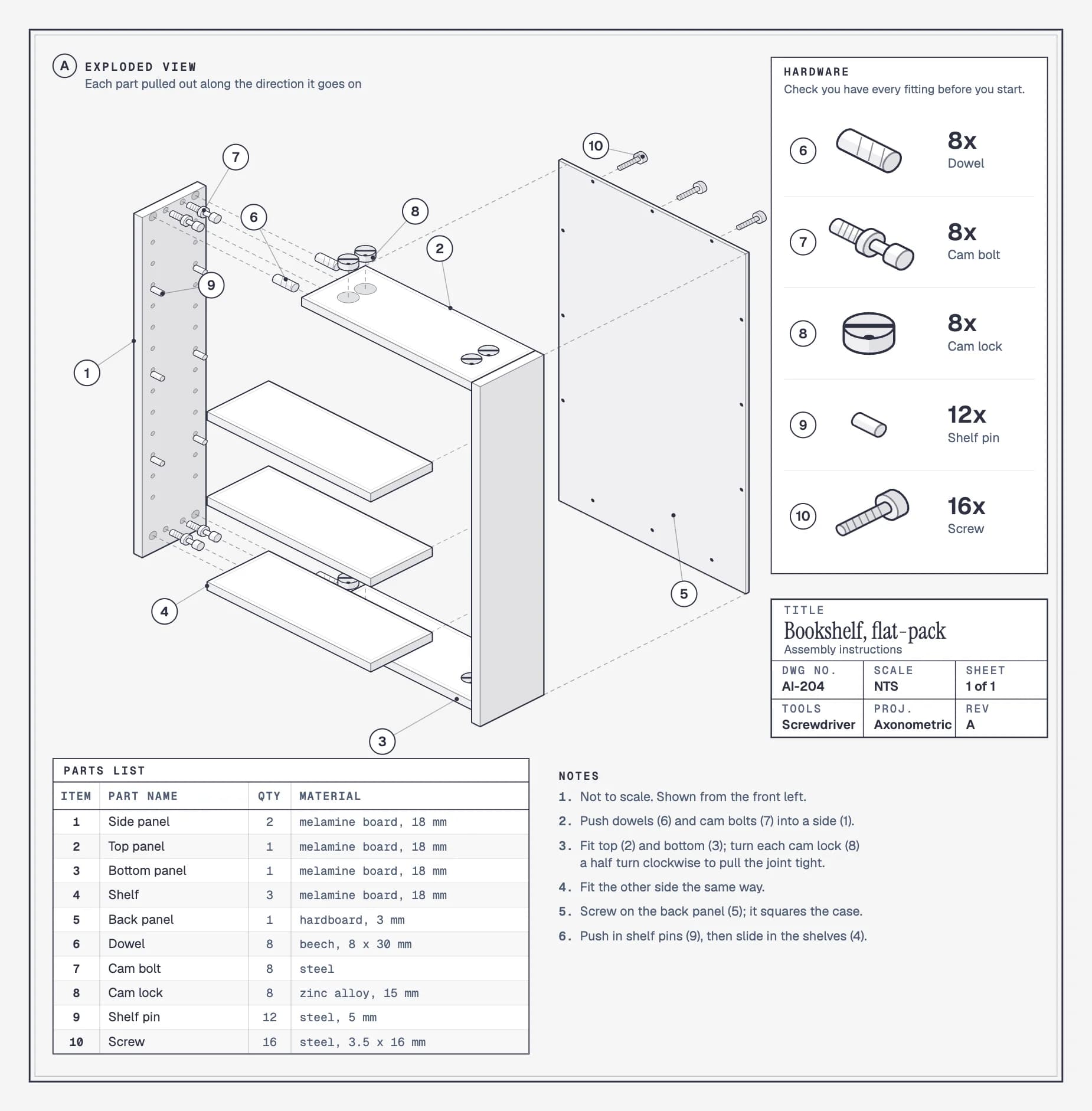
“Make assembly instructions for a flat-pack bookshelf: two sides, top, bottom, three shelves, back panel, 8 dowels, 8 cam bolts, 8 cam locks, 12 shelf pins, 16 screws. Pull each part out the way it goes on, number everything, and add a hardware box with counts, a parts list and short numbered steps.”
Furniture instructions are exploded views with one extra job: every screw, dowel and cam lock has to be counted. Here the hardware gets its own numbers and a check-list with counts (8 dowels, 8 cam bolts, 8 cam locks, 12 shelf pins, 16 screws), and the parts pull out in the direction each one goes on: the side sideways, the shelves forward, the back panel backward. Six short numbered steps refer to the same numbers, so the drawing and the instructions never disagree.
A house, as an exploded axonometric
Make one like this
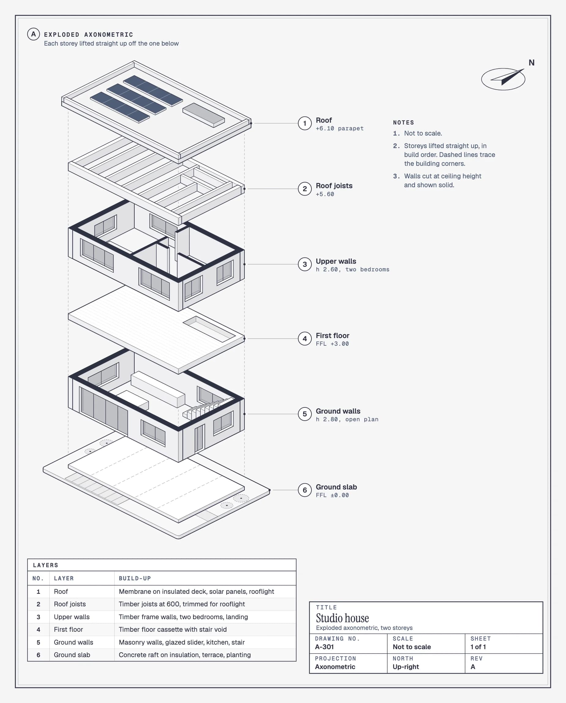
“Draw an exploded axonometric of a small two-storey house for an architecture board: ground slab, ground-floor walls, first floor, upper walls, roof joists and roof, each lifted straight up. Cut the walls at ceiling height so the rooms show, label each layer with its level, and add a north arrow and a layers list.”
In architecture, the exploded axonometric shows how a building is layered: ground slab, ground-floor walls, first floor, upper walls, roof joists and roof, each lifted straight up from the one below. Walls are cut at ceiling height and drawn solid on top, the way plans show cut walls, so you can see the rooms inside. Each layer carries its level (FFL +3.00 for the first floor), the layers list gives its build-up, and a north arrow sets the orientation. It is a staple of student presentation boards because one drawing explains the whole construction.
A small computer, for a product teardown

Make one like this
“Draw an exploded view of a small single-board computer in its case: case, board, heatsink, fan, lid, from the bottom up. Label each part next to it with a short spec, and colour only the board.”
With only five parts, numbers and a list would be overkill. Here each part is named next to it with a short spec, and one part, the board, is picked out in colour because it is what the drawing is about.
How to draw an exploded view by hand
- List the parts in assembly order. Write them down from the first part that goes in to the last. This list becomes your numbering and your parts list.
- Pick the axis. Usually the direction the parts go together: straight down for an engine or a building, sideways for a hinge. Most drawings use one axis; complicated ones use two.
- Draw it assembled, in isometric, very lightly. This fixes the size and position of every part.
- Slide each part out along the axis. Redraw each part a set distance further along the axis than the one before. Keep the gaps even and don’t rotate anything.
- Add the trace lines. Dashed lines along the axis, through the centres of the parts, show how they go back together.
- Number the parts and add the parts list. Balloons with leader lines, in assembly order, and a list with each number, name and quantity.
How to make an exploded view drawing with AI
The quickest way is the one at the top of this page: add Diagram to Claude or ChatGPT and describe the object and its parts. Given the prompts on this page, Claude drew a ballpoint pen, a flashlight and a full engine drawing sheet with sixteen numbered parts on the first try, then fixed its own small layout problems. Check what it assumes about your object, and correct it in plain words. The drawings on this page were made another way, by an AI coding tool. The free diagram-design skill teaches the AI to compute every corner from one projection, so parts line up and the gaps stay even, instead of guessing like an image generator does. You describe the object and its parts; the AI does the geometry.
- Add the skill to a coding agent. In a terminal, run
npx skills add cathrynlavery/diagram-design. It works in Claude Code, Cursor, Codex and GitHub Copilot. - Connect Diagram, so each drawing is saved at a link you can open, share and update:Claude CodeCursorCodex CLIVS Code + Copilot
- Ask for it, naming the parts in order. The more specific the list, the better the drawing:
 Claude Code
 Codex CLI
- “Draw an exploded view of a single-cylinder engine along the cylinder axis: crankcase, crankshaft, connecting rod, piston with rings and pin, cylinder block, head gasket, cylinder head, valves, valve cover. Number every part, add trace lines and a parts list, and give me the link.”
- “Make an assembly drawing for a flat-pack bookshelf: two sides, top, bottom, three shelves, back panel, 8 dowels, 8 cam locks, 12 screws. Explode it the way it goes together and put quantities in the parts list.”
- “Draw an exploded axonometric of a two-storey house for a presentation board: slab, ground-floor walls, first floor, upper walls, roof structure, roof. Label each layer and add a north arrow.”
Then check it against the real object: is every part there, in the right order, and does the parts list match the numbers? Ask for corrections in plain words and the same link updates. Want it to move? Ask for the animated version, where the object starts assembled and pulls apart once.
Exploded views and other technical drawings
An assembly drawing shows the object put together with the same numbered balloons; an exploded view pulls the parts apart so hidden ones show. A cutaway drawing leaves the object assembled and removes a slice of its outside to reveal the inside, which suits things that don’t come apart. A section view cuts straight through along a plane, for exact internal dimensions. And an isometric drawing is the projection most exploded views are drawn in, not a kind of drawing on its own.
If you already have a 3D model, CAD software such as SolidWorks, Fusion 360, Inventor or Onshape makes the exploded view from it and puts it on a drawing sheet with balloons and a parts list. The approach on this page is for when you don’t have a model, or need a clear illustration rather than a manufacturing drawing.
Questions
- What is an exploded view drawing?
- A drawing of an object with its parts pulled apart along the direction they assemble in, so you can see every part, what sits inside what, and the order they go together. Parts are numbered or labelled, usually with a parts list. It is also called an exploded diagram, an explosion drawing or an exploded assembly drawing.
- What is the purpose of an exploded view drawing?
- To show how something goes together. Assembly instructions, repair manuals and parts catalogs use them so a reader can find a part by its number and see where it fits. Designers and students use them to explain a product, and architects use exploded axonometrics to show how a building is layered.
- What are the lines in an exploded view called?
- The dashed lines that show the path each part travels to assemble are trace lines, also called explode lines or centre lines. The thin lines from a part to its number are leader lines, and the circled numbers are balloons.
- What is an exploded axonometric drawing?
- An exploded view drawn in axonometric projection, where parallel lines stay parallel and nothing shrinks with distance. Architects use it to show a building’s layers, from the ground slab to the roof. Isometric is one kind of axonometric.
- What is the difference between an assembly drawing and an exploded view?
- An assembly drawing shows the object put together, with each part numbered. An exploded view pulls those same parts apart along their assembly direction, so parts hidden inside become visible. Manuals often show both.
- How do I make an exploded view in SolidWorks, Fusion 360 or Inventor?
- If you have a 3D model, use the software’s own exploded view feature: it moves the parts of the model for you and can put the result on a drawing sheet with balloons and a parts list. The methods on this page are for when you don’t have a model, or want a clean illustration quickly.
- Can AI make an exploded view drawing?
- Yes. An AI coding tool such as Claude Code, Cursor or Codex, with the free diagram-design skill, draws exploded views like the ones on this page from a list of parts. Image generators can make an exploded-looking picture, but the parts, numbers and proportions are guessed.
- Is it free?
- The diagram-design skill is free and open source. Diagram, which saves each drawing at a link you can share, is free for your first 5 diagrams.